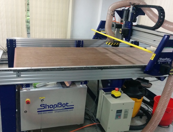
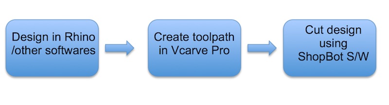
The Shopbot is a CNC that can cut materials like wood, acrylic and even soft metals. Based on the design, you can cut 2D and 3D files. In order to use the machine, three different software components are used:
1. A design software like Rhino to model 2D or 3D shapes.
2. Vcarve pro software to create the toolpath for the machine.
3. Shopbot software to set the origin for the machine and feed the toolpath file.
In order to cut a 2D design file on the Shopbot, you need to follow the steps below:
Step 1: Creating the toolpath for the machine
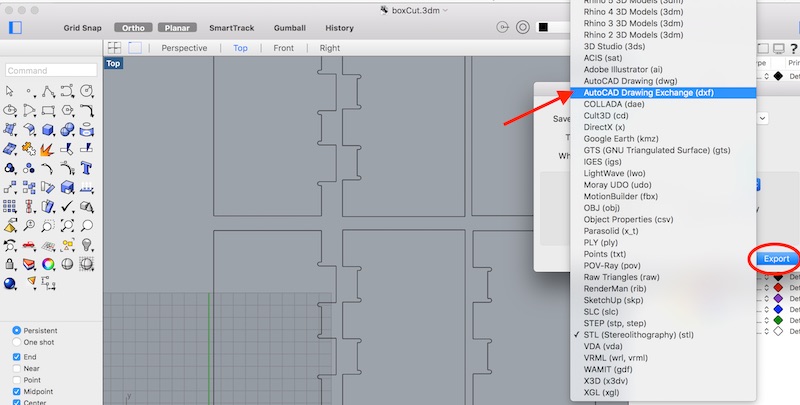
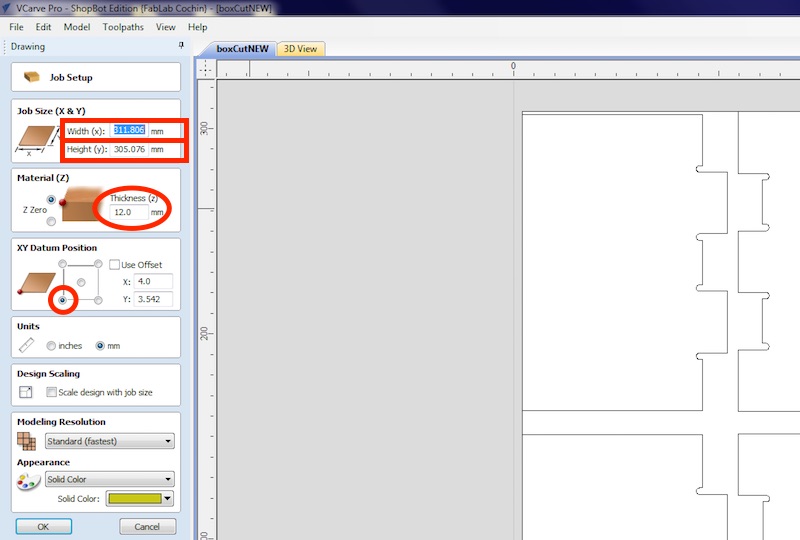
Assuming, you have a 2D design file (if you don’t, then you can make one in Rhino and export it as a .dxf file), you need to open it inside the Vcarve Pro software. Upon opening, set the size of the material based on the available dimensions available on the board you are cutting. The material thickness is taken as 12mm (depending on the plywood sheet). And be careful to uncheck the “offset” option and set the origin as the left bottom corner:
There are primarily three operations that can be done using the ShopBot: Drilling, pocket and profile.
Drill
First we start with the Drill operation to mark the holes for the portions which we want to drill down using screws, so that they are firmly held in place. Use the circle tool to draw circles of diameter 3mm on opposite sides of each piece of the design.
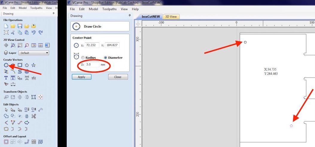
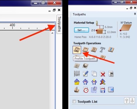
And then select only the circles drawn and click on the “Toolpath” option on the top right corner and pin it down so that it doesn’t move. Set the Start depth as 0 and Cut depth as 4mm. And from the Tool End section, click on “Select”.
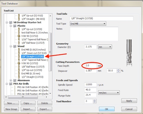
Set the diameter for the tool as 6.35mm and the Pass Depth (the depth at which each cut is done) as 3.5mm. The Spindle Speed can be set to 12,000 rpm and you can use higher speeds for better finish.
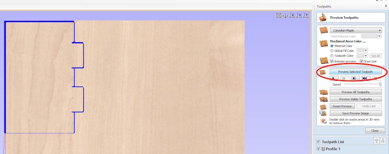
Now click on “Preview selected toolpath” to watch the simulation of the drilling being done on the material. Next, click on the “Save” button to save the toolpath.
Next, select the circular portion of the design of which you want to remove only the top few layers and unselect everything else. Click on the “Pocket” button and set the cut depth to 8mm. Set the stepover (radius of the smallest circle of which the machine removes the material) as 1.5mm.
Then click on “Preview selected toolpath” to view the simulation of the engraving or material removal. If you are satisfied, click on the Save button to save the toolpath.
Profile
This operation is used to cut a portion of the material from the whole board. Select the lines which you wish to cut and click on the Profile button. Set the Cut Depth to 14mm.
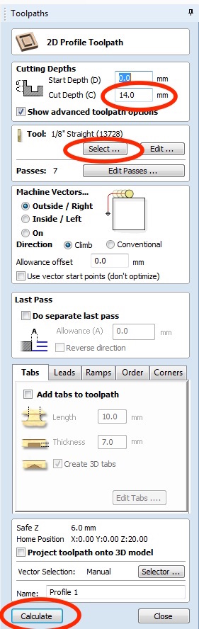
Next, set the Pass depth from the tool select menu to be 3.5mm or 2mm depending on the finish or the speed at which you want the operation to be over. Make sure to switch the Machine Vectors to ON.
And also if needed add tabs to the cut, to prevent the material from jerking in the machine. Set the length: 5mm, thickness: 7mm and click on edit tabs to add the tabs manually on the shape. You can then later view the preview for the operation on the ShopBot, like a simulation.
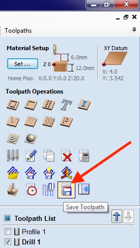
Now, make sure to save the drill toolpath separately and the pocket and profile toolpaths together (by selecting the pocket and profile toolpaths and saving them together). The order for doing it should be: Drill→ Pocket → Profile.
Step 2: Setting up the machine
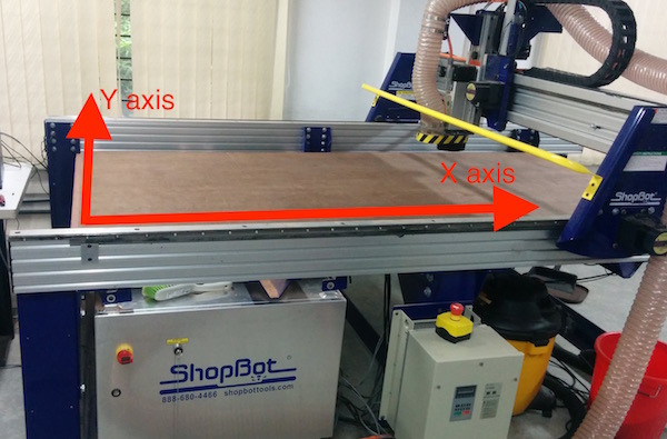
Before using the machine, first you need to understand its orientation. This is required in order to correctly align the design in the area of the material where you wish to cut. The longer axis of the machine is X and shorter one is Y. Like in figure below:
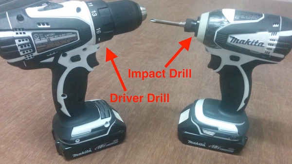
Place the material you wish to use on top of the sacrificial layer and screw it down using power drills (impact drill).
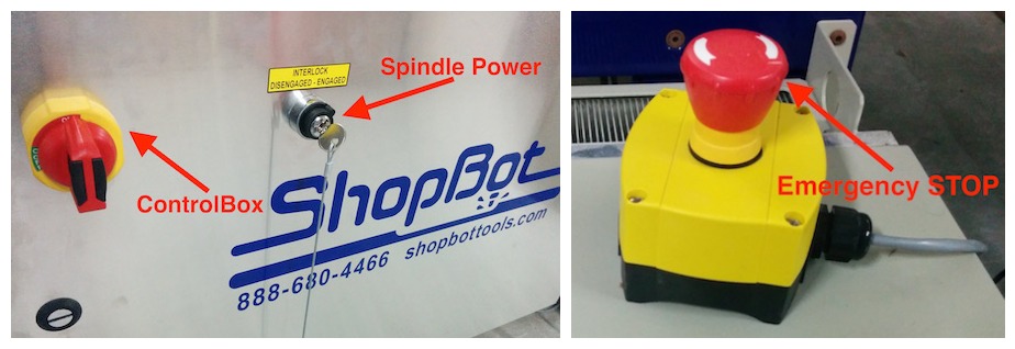
Next, power ON the machine by switching ON the main power supply and the control board switch. Check to see if any of the emergency stops are engaged, release them if they are.
Now open the ShopBot software and use the arrow keys to move the spindle to the portion where you wish to cut. The origin for the machine is the bottom left corner (check first image of step two)
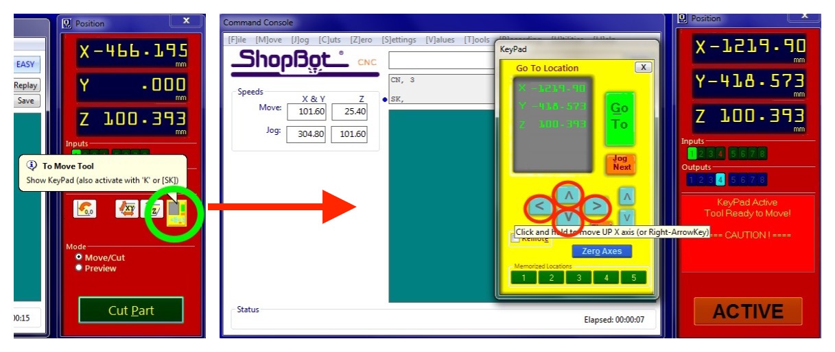
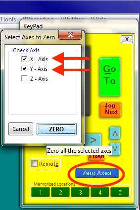
Click on the [Z]ero option from the toolbar or the ZeroAxes button from the console and click X and Y axes. Move the spindle head to the portion which you want to set as the origin and click on Zero axes button and check X and Y axes. And close the move console.
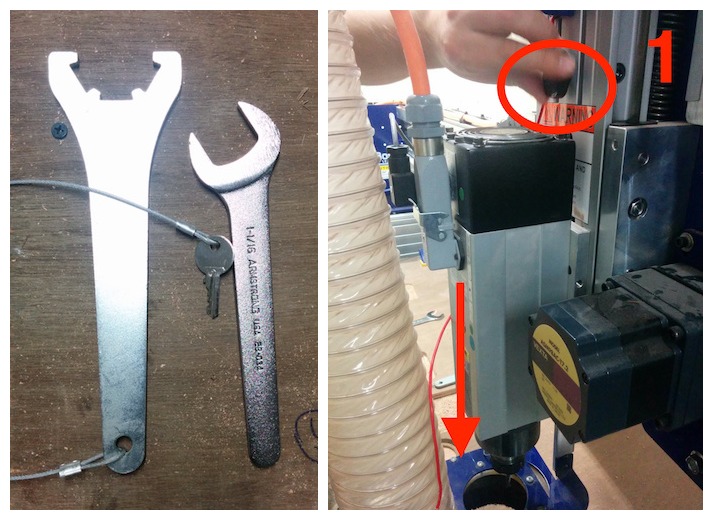
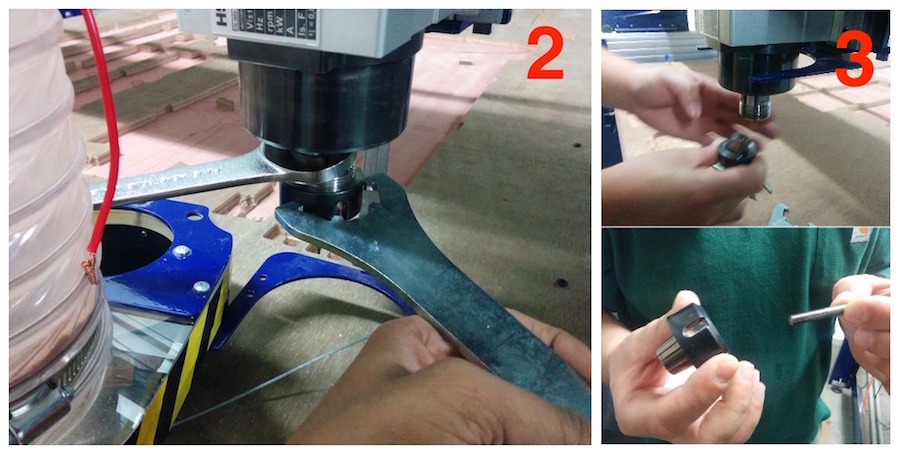
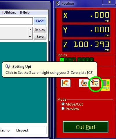
Next, you need to set the Z axis origin. To do this, click on the Z axis option from the [Z]ero toolbar dropdown and follow the instructions. Remove the steel plate from the spindle block and clip the alligator clip on to the cullet. Place the steel plate below the mill bit and click “OK” on the dialog box that asks you to do this (follow the figures below).
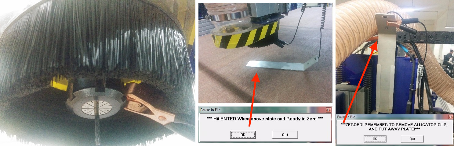
The machine makes the spindle move down and the mill bit touches the plate, this happens two times in order to figure out the exact Z axis height. After this, remove the alligator clip and place the metal plate back to its earlier position.
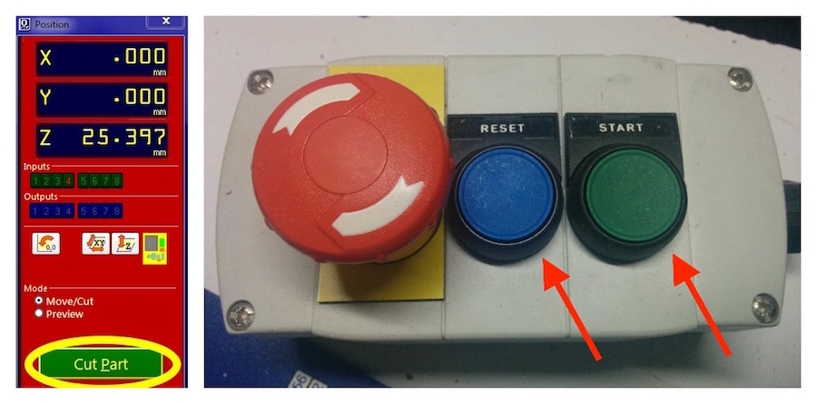
Now, we are ready to cut the part. Click on “CUT PART” and open the first drill toolpath that was created through Vcarve Pro. Press the REST button on the machine to reset it and press START button when the computer asks you to. The spindle starts and begins drilling the paths, turn on the Vacuum pump to suck the dust from the machine.
After it completes, drill screws through the parts using the hand drill. And then repeat the same steps for cutting the part by loading the next toolpath file for the pocket and profile operations and wait for the completion. A product obtained after completing the three operations:
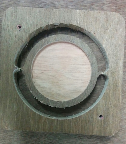
The product obtained from my design file:
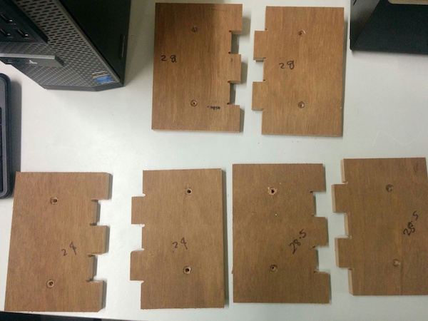
Download files: BoxCut.dxf, BoxCut.3dm