This day we started off with Kokopelli. Curious to know the meaning of the word,I tried searching for it. And I found out that it’s the name given to a humpbacked flute player, considered as a fertility Deity.
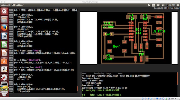
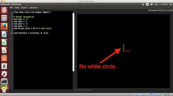
Well here we are using Kokopelli software developed by Neil Gershenfeld for making circuit board designs. It uses a coding environment having an output window for showing a graphical representation of the code as shown here:
We covered the following during the day:
• Installing Kokopelli
• Opening a .cad file using it
• Figuring out the meaning of each module (PCB parameters, components, etc)
• Added a new set of components and drew the traces for it
Installing Kokopelli
Step 1:
To install this, first I had to download the Koko_retro.zip file from here: link.
Step 2:
Next I had to install the dependencies for python using this command:
sudo apt-get install python python-wxgtk2.8 python-dev python-pip gcc g++ libpng12-dev libgif-dev make bash okular libboost-thread-dev libboost-system-dev cmake
(refer: http://kokompe.cba.mit.edu/downloads.html)
Step 3:
And then I used this command to install numpy (refer: https://github.com/mkeeter/kokopelli/wiki/Installing)
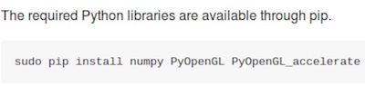
sudo pip install numpy PyOpenGL PyOpenGL_accelerate
Step 5:
Next, I unzipped the koko_retro.zip file and navigated to the newly created folder from the terminal and used the following commands:
Problems faced
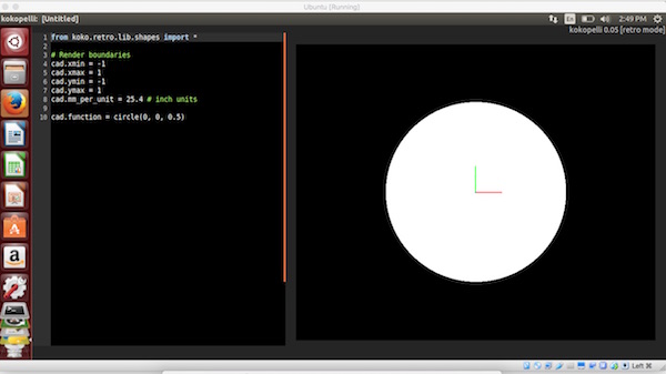
When launching the software, I noticed that the circle was not appearing on the graphical interface and made me aware that it was not installed correctly. After which, we tried using this command: sudo make install in the folder of the install, which solved the problem. A screenshot of the problem:
Editing a design
First download this .cad file from here: link
And then open the file from Kokopelli.
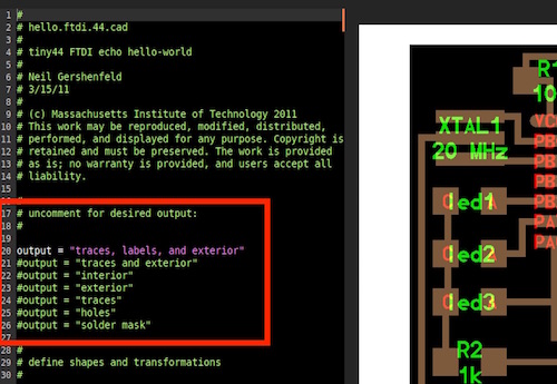
# uncomment for desired output:
#output = "traces, labels, and exterior"
#output = "traces and exterior"
#output = "interior"
#output = "exterior"
#output = "traces"
#output = "holes"
#output = "solder mask"
Just uncomment the kind of output you want from the above lines (line no: 21)
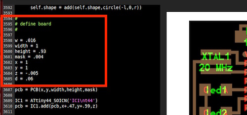
And to edit the width of the board and other parameters, go to line 3595. You can edit these lines to change the dimensions and other parameters:
w = .016
width = 1
height = .93
mask = .004
x = 1
y = 1
z = -.005
d = .06
pcb = PCB(x,y,width,height,mask)
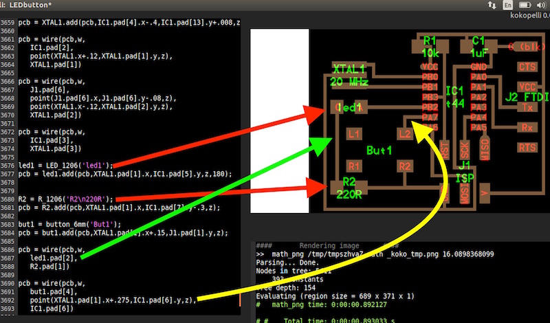
Next, I tried to do the following:
The coding required to do the four operations above are marked with arrows in the figure below: