Today we started off by cleaning up the workspaces. As Francisco had mentioned, this is in order to prevent the “Barcelona effect” by which he means to avoid situations where people have to go on keep looking for tools and waste their time by doing so.
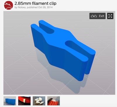
After that, he recommended making 3D printer based designs for objects to hold:
We found this file to hold 2.85mm reels tightly: http://www.thingiverse.com/thing:520205/#files
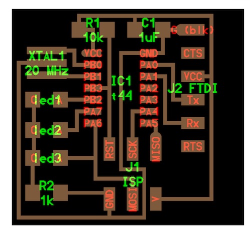
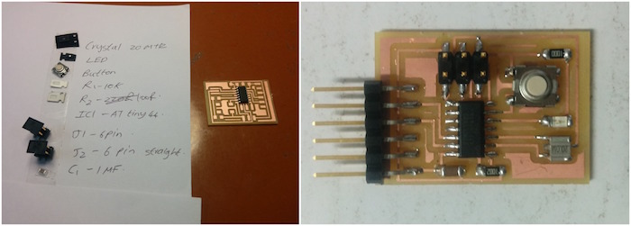
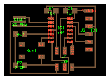
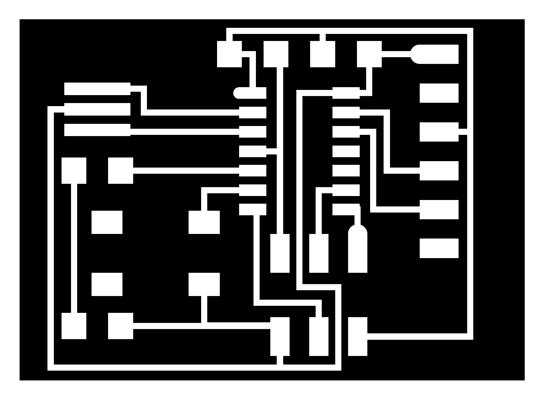
Next, the task for the day was to design a board using Kokopelli by adding a LED and button to Neil’s existing helloworld.cad board. And then to mill the board using Modela and solder the components on to it. The board was designed as so: (not to scale)
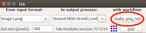
Next, the board’s traces, interior and exterior .png files were exported. (Learning 1- Make sure that the file is named with an extension .png, otherwise the export wouldn’t work). The files were then taken to the Modela and the design file was opened using FabModules. To learn more about using the Modella, check this (tutorial link).
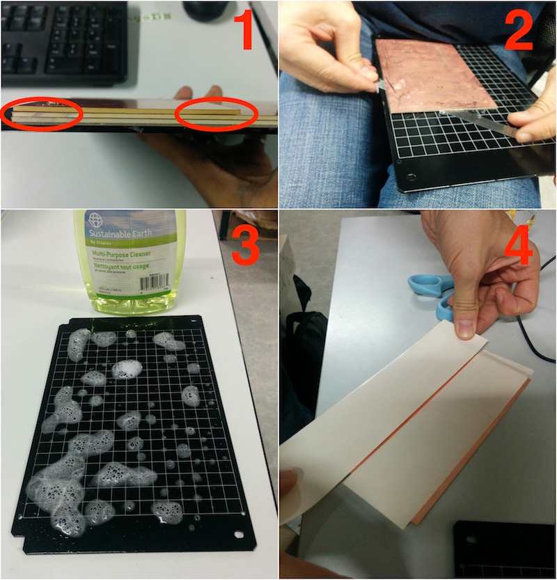
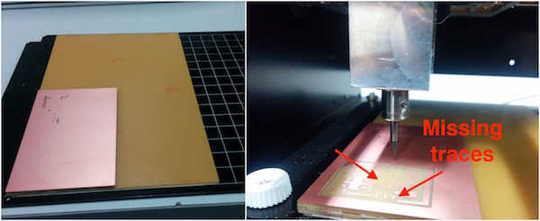
Before moving on to milling the board, we noticed that the surface plate of the Modela was very dirty due to the residues from the double side tapes used on it. This caused the new board which I put, to be bent and unevenly affixed on top of the sacrificial layer (check the figure below). Moreover, there were two sacrificial layers already on the board which amplified any bents on it. Therefore, it was taken out and cleaned.
A new sacrificial layer was then added using a paper protected double side tape with the copper side facing the plate.
Next, I pasted the Cu board for making my circuit on top of the sacrificial layer and started milling. Learning 2- However, the mill was not good as the traces were peeling off from the surface. Thus it was concluded that the end mill was attached with too much length from the top which caused it to mill more than I wanted.
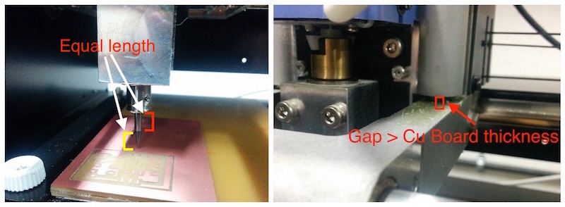
The process was then stopped and the mill was removed and put back together making sure that the length of the mill shaft is minimally exposed and the gap between the spindle module and the chassis of the machine was decent. As shown:
The file for the circuit design was also rotated using the Ubuntu stock photo viewing software in order to position the design on the remaining free portion of the copper board. Learning 3- Note down the dimensions of the original design before rotating and resize the newly rotated design from FabModules using the earlier noted dimensions.
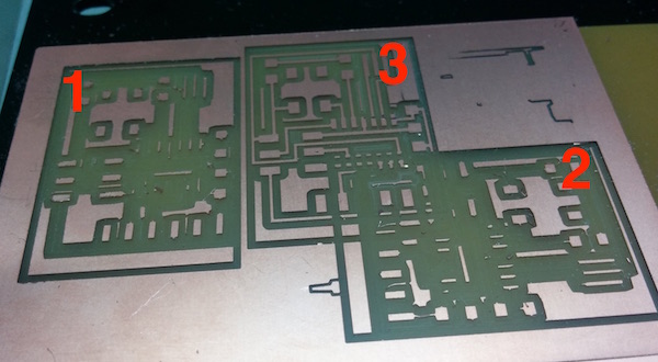
However, even after performing this, all the traces had not perfectly come through. Even though, it was much better than before. The firt two attempts were diagnosed to be caused due to improper spindle length and chassis gap. However the third test attempt was succesful, the reason of which can be found by reading below. All the failed attempts at making the circuit:
Learning 4- We figured out the problem that the resolution set by default from Kokopelli was 10 and which wasn’t enough for the machine to mill effectively. The resolution was later set to 50 and which solved the problem. And the board was obtained like so:
Download files: LEDbutton.png, traces.png, exterior.png and .cad file
The board was then programmed by first burning the bootloader from Arduino by using the FabISP. You can read about the journey below.
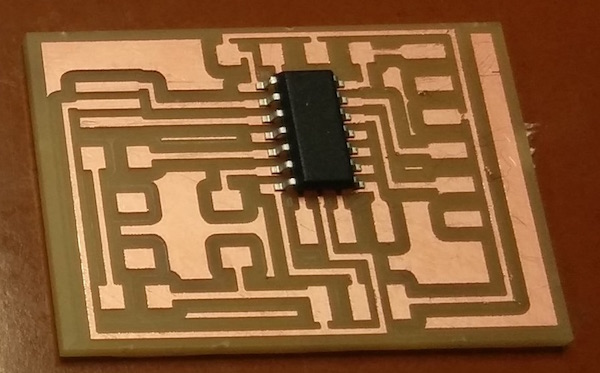
After soldering the board milled from the Modela, it looks like this:
After that I installed Arduino 1.6.6 from the website: https://www.arduino.cc/en/Main/Donate
And then also added the support for adding ATtiny44 chip to Arduino IDE. I followed the steps stated here: http://highlowtech.org/?p=1695. After installing the support, you get to see the ATtiny board from the boards menu of arduino:
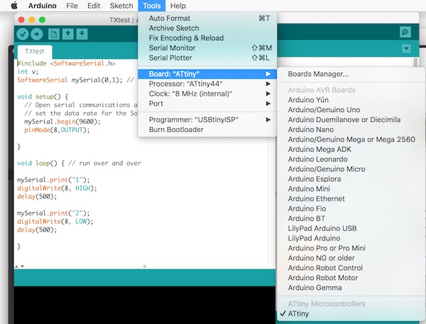
After that I used my ISP made from the other day and set the following settings:
And then plugged in my ISP and connected it to my newly created board. I was then able to “Burn bootloader” and successfully uploaded a sample program to the board. Make sure the ATtiny board you are using has an external 20MHz crystal, if it doesn't then trying to burn a program using the settings for an external crystal can break your board.
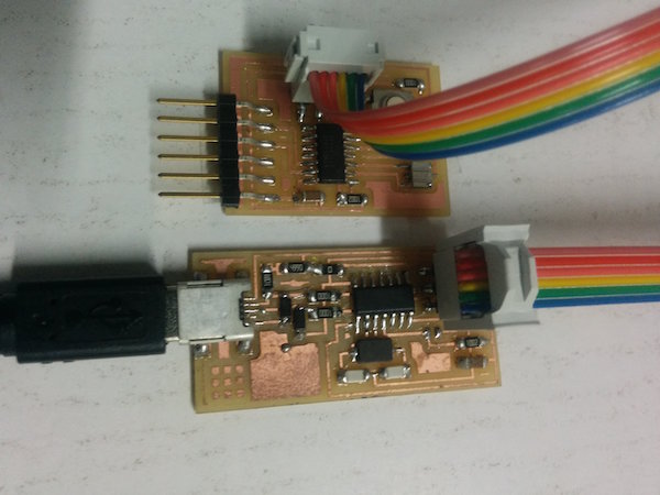
An interesting thing was that the ISP I made seems to be only detected in my Mac OS, when I tried plugging it on Francisco’s PC running Ubuntu, it was not being detected.
And correct way of making an ISP cable:
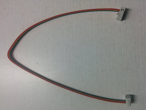
The ISP cable I made was shorted in one of the ends which made it not work on the first attempt.