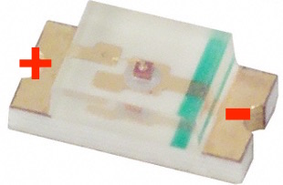
Learning 1- In SMD leds, the edge having the green line is cathode (negative). I had to resolder the LED on to the board since the polarity was reversed.
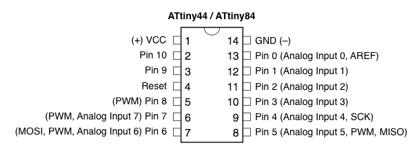
I uploaded the blink example code using Arduino on to the ATtiny44 board I made the other day (all the programs created can be found embedded in this page). I had to make sure that the pin out of the ATtiny44 was compliant with that of Arduino as shown in the image here:
The program was successfully uploaded on to the board through the FabISP (which I made, check here) using the following settings:
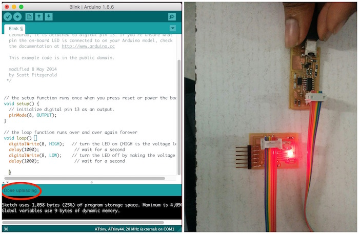
The code for blinking an LED:
void setup() {
  // initialize digital pin 8 as an output.
  pinMode(8, OUTPUT);
}

// the loop function runs over and over again forever
void loop() {
  digitalWrite(8, HIGH);   // turn the LED on (HIGH is the voltage level)
  delay(1000);              // wait for a second
  digitalWrite(8, LOW);    // turn the LED off by making the voltage LOW
  delay(1000);              // wait for a second
}
Next, I tried using a button with ATtiny44. I programmed pin 6 on the board (Arduino pin 7) to be pulled up using command: pinMode(7,INPUT_PULLUP). And then used an “if” statement to switch an LED ON when pressing the button, and to switch it off when it is de pressed.
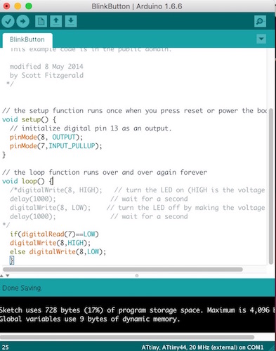
The code:
void setup() {
  // initialize digital pin 13 as an output.
  pinMode(8, OUTPUT);
  pinMode(7,INPUT_PULLUP);
}

// the loop function runs over and over again forever
void loop() {
 if(digitalRead(7)==LOW)
  digitalWrite(8,HIGH);
 else digitalWrite(8,LOW);
  delay(500);
  }
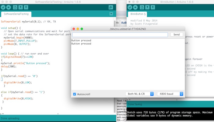
Next, I was trying to get the serial communication for the tiny board setup so that I can communicate with it from my PC. I tried using the software serial example code from File-->Examples-->SoftwareSerial. But was not able to get it working even after changing the pin nos to 1,0 for RX and TX.
Learning 2- I was later able to get the Serial communication setup when Francisco pointed out that the board was designed having the RX and TX with respect to the FTDI cable. And serial cables are connected between RX—>TX and TX→RX. So I edited the command mySerial.begin(1,0) to mySerial.begin(0,1) (RX and TX).
I tried printing “Button pressed” through Serial, when I pressed the button on my board.
And also added the code to switch ON my LED when I send a character “1” through Serial and to switch it OFF when I send “0”.
Learning 3- I noticed that when I was sending characters 1 and 0 to control the LED, at times the board wasn’t able to detect the 1’s I was sending. And later I found the solution to it by initializing an int variable to hold the serial characters:
int v; v = mySerial.read();
and using ‘v’ to compare the characters within ‘if’. This solved the problem which was created when I used “if(mySerial.read()==’1’) to compare directly. The code:
#include <SoftwareSerial.h>
int v;
SoftwareSerial mySerial(0,1); // RX, TX

void setup() {
  // Open serial communications and wait for port to open:
  // set the data rate for the SoftwareSerial port
  mySerial.begin(4800);
  pinMode(7,INPUT_PULLUP);
  pinMode(8, OUTPUT);
}

void loop() { // run over and over
v=mySerial.read();
if(digitalRead(7)==LOW)
{
  mySerial.println("Button pressed");
  delay(200);
}

if(v=='1')
{
  digitalWrite(8,HIGH);
}

if(v=='2')
{
  digitalWrite(8,LOW);
}
}
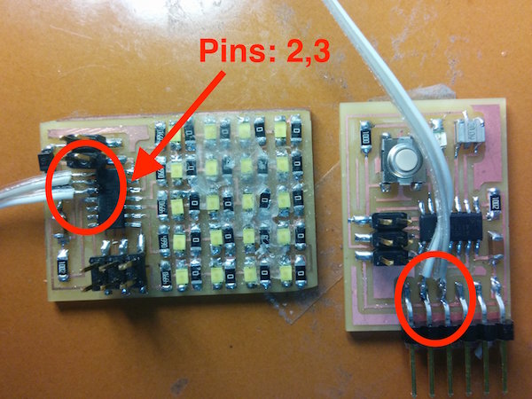
Later, I also tried to start testing serial communication between two ATtiny boards. For doing this, first I soldered two pairs of wires for RX and TX to both ATtiny boards like so: