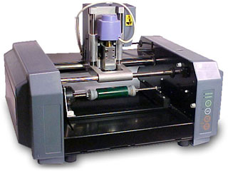
This page takes you through the process of milling PCBs using a Roland Modela MDX-20.
The Modela is one of the most used machines in our FabLab. Its a tiny desktop CNC that can mill PCBs, create 3D models on wax and even scan in 3D. It is preferred for making PCBs using FR-1 copper boards as it doesn’t leave any chemical wastes. But do not use it to mill FR-4 boards as it creates a lot of dust from fibre glass and which is toxic when it is inhaled. Here, I am going to be taking you through the process of how I milled a FabISP board on the modela.
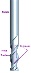
To become an expert in using the machine, you need to know the exact drill bits you need to use with the machine. They are classified based on their ends (flat end/ball end), their number of flutes (2/4) and their diameter. Parameters of a drill bit based on the picture below:
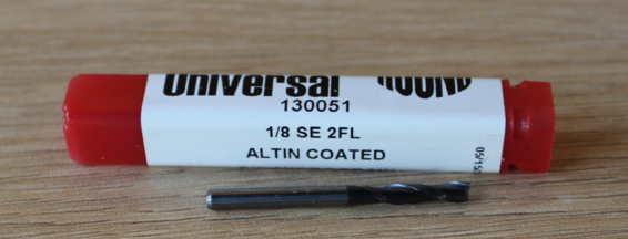
⅛ in - Diameter (3.175 mm)
2 FL - 2 flutes
BN - Ball Nose
Length - Short (regular)
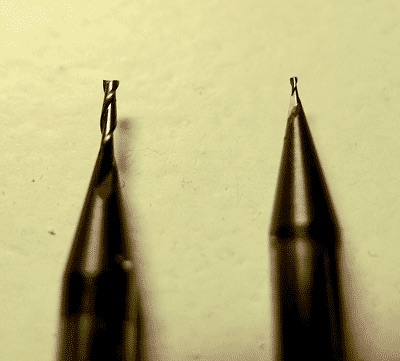
Here, we are going to be milling PCBs and for doing that we use the following two bits:
What are the stuff required to do this?
How it works?
Step 1: Creating the design file
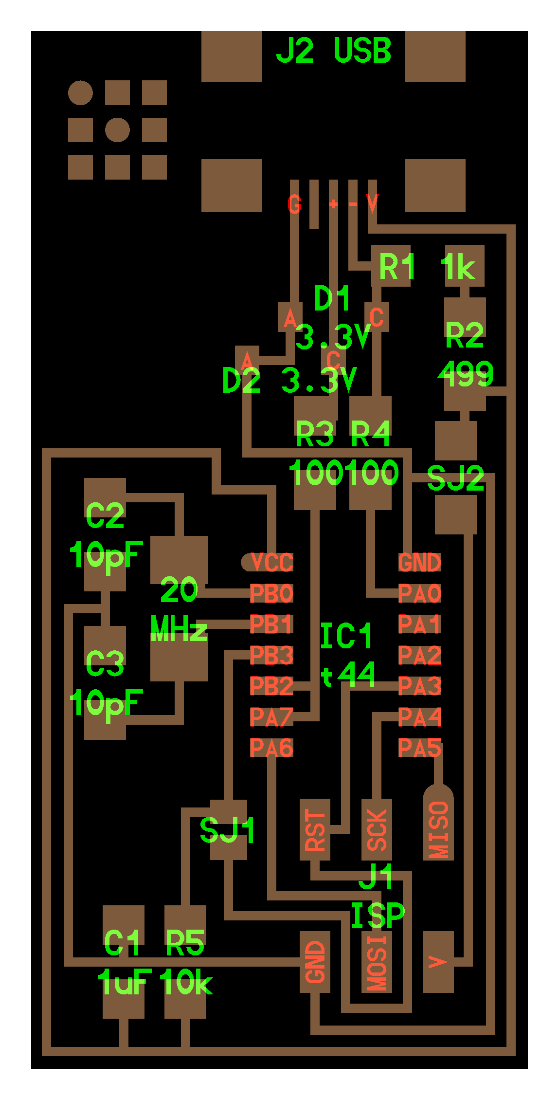
To do this you need to use softwares like Eagle to design and create the board layout for your PCB. You will get a .png exported design file like so from the software: (not to scale)
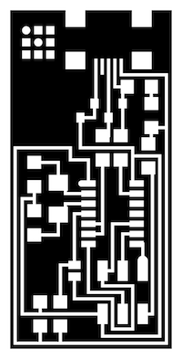
The original files used for this can be found at the bottom of the page.
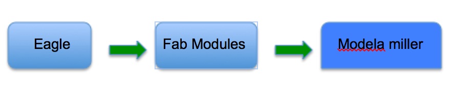
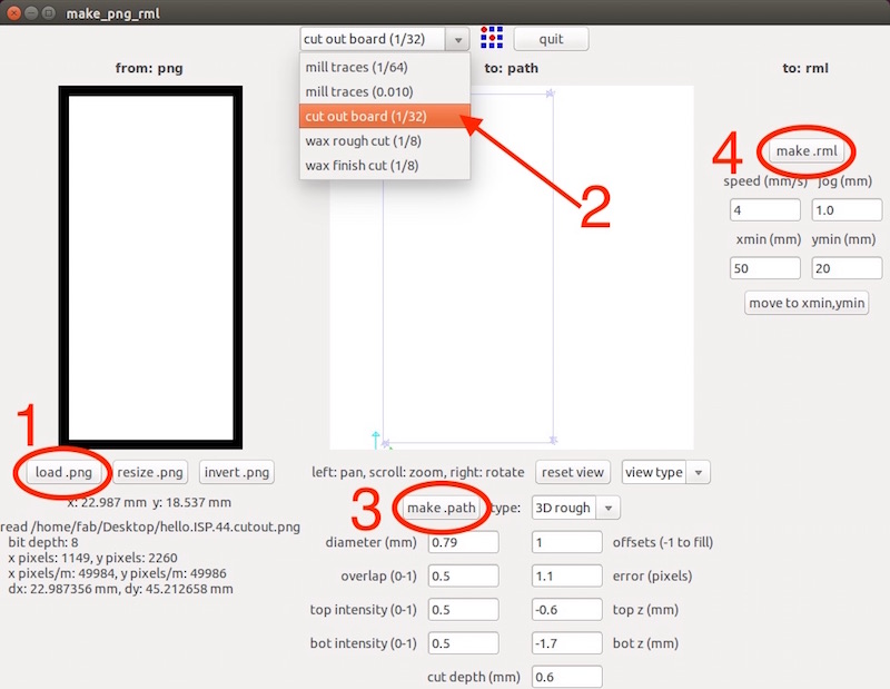
Step 2: Using the Fab Modules
Fab modules is a software interface prepared to talk to all the machines in a Fab Lab. It has been created in the hope to eliminate all middle ware required to be used to talk to each of the machine in the lab. If you do not have Fab modules installed in your linux PC, you can check out this tutorial for doing it: link.
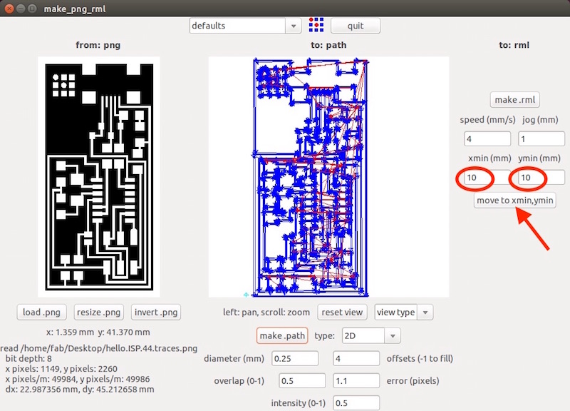
After installing the Fab modules, next select input and select file type as “.png” and the output as “Roland Modela MDX-20”.
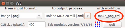
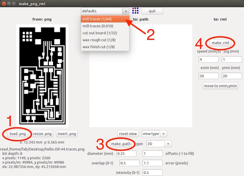
Load the circuit design file and click on "make_png_rml"
Select the default parameters for a 1/64” mill bit and other parameters for Diameter: 0.4 and Offset (which is the number of passes it goes around the circuit trace to remove the material) with a value of 4. If you use -1 as the offset, the mill removes all the material except for the traces. And then click on "make .path"
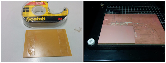
Step 3: Place the copper board on the plate
Use two strips of double sided tape to firmly fix the copper board on top of the sacrificial layer.
Step 4: Preparing the machine for milling
Make sure the mill bit on the machine is 1/64 else replace it with the correct bit by loosening the nut on the head using an Allen key. After this, switch ON the machine.
You need to home the machine or set the origin point for the milling operation to start from. To mill the PCB on the required portion of the board, move the drill bit by editing the Xmin and Ymin values on Fab modules and clicking on “Move”.
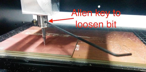
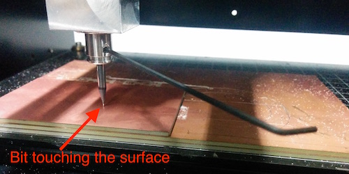
Next step is to set the origin point for the Z axis. To do this, bring the milling bit down by pressing the “Down arrow” button on the machine till it almost reaches the board and then loosen the bit using the Allen key.
The bit should slowly fall down and touch the surface of the board, after which the mill bit should be tightened by using the Allen key.
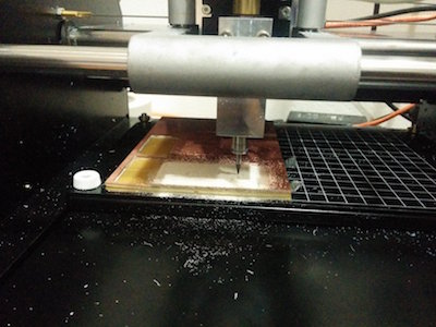
Step 5: Milling the board
Click on the “Make .rml” button and send the machine file to the Modela by clicking on “Send It!”. After which the machine will start milling and removing copper from around the traces.
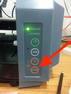
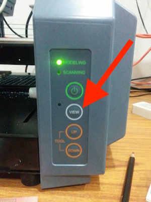
Click on the “View” button on the machine to pause the milling and see the progress on the board. To resume, press on “View” again.
Step 6: Cutting out the board
After milling the board, the milled portion should be cut off from the remaining board using the Modela. To do this, first the mill bit should be replaced with a 1/32” one. Loosen the nut on the head and replace the bit.
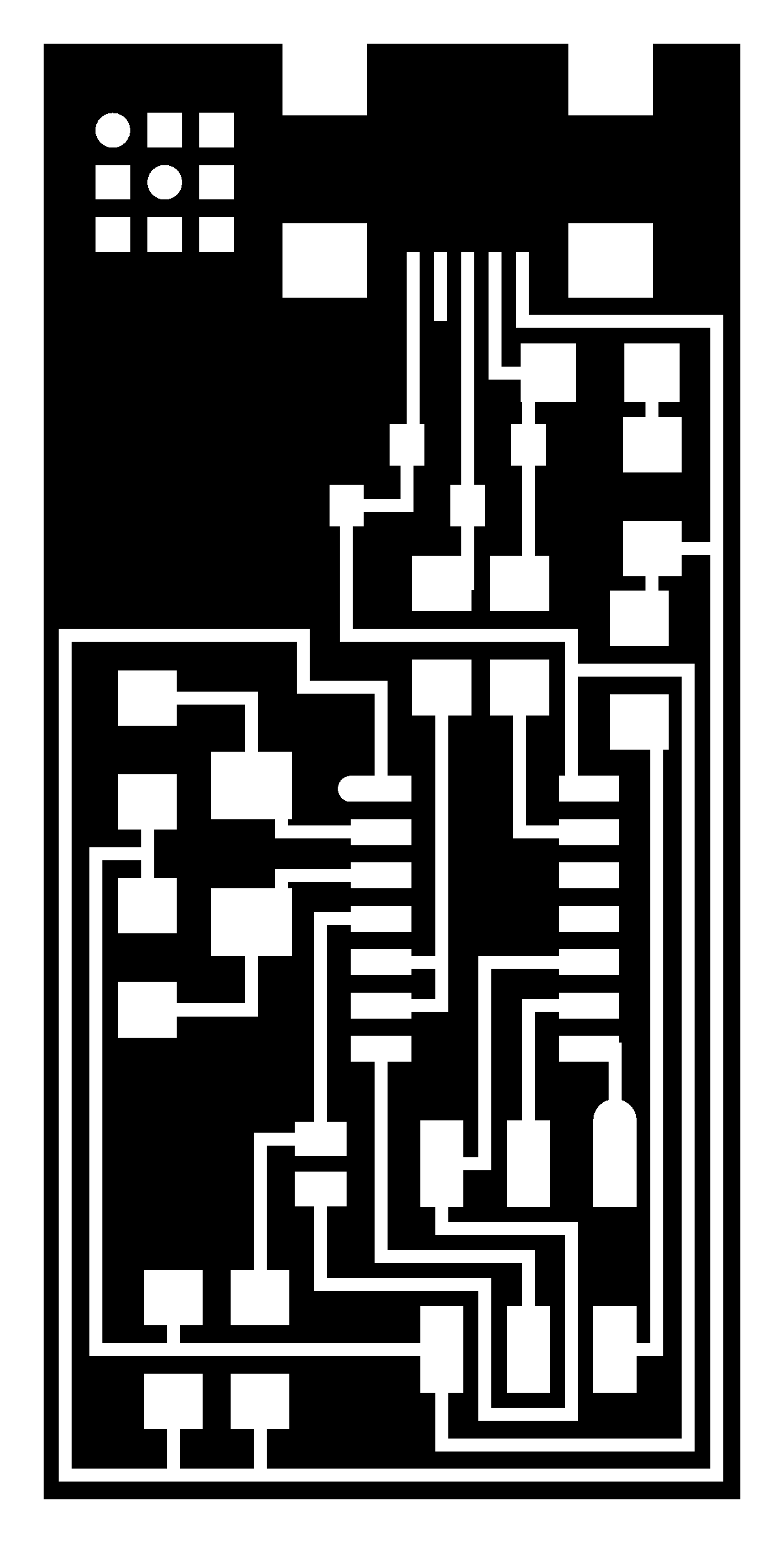
Next, the outline for the cut should be loaded as a .png file using Fab modules, something that looks like the figure below (not to scale). It should be of the exact dimension of your PCB.

Now change the setting on the Fab modules to 1/32 for cutting, click on “Make path” and then “Make .rml”. Be careful to not change the origin for the machine and then click on “Send It!” to cut the PCB.
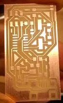
After milling, you will be able to remove the PCB from the board and be careful to not touch the surface traces as it would make soldering a lot more difficult. I got something like this after the milling:
Download files: fabISPtraces.png, fabISPinfo.png and fabISPoutline.png