The idea to this project came to me based on an insight that was shared by Francisco during our training. He talked about how his lab only has stools for people to sit on, which being very uncomfortable succumbs the person to stand up and move around. In our case, we had very comfortable rolling chairs for sitting and reclining, which can get you lazy real quick.
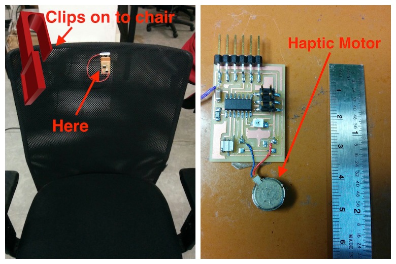
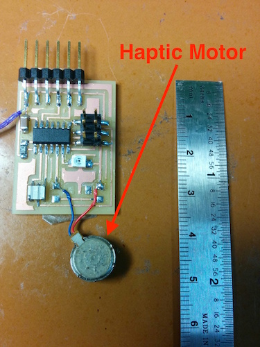
In this project, I wanted to solve that problem by creating a sleek gadget which when plugged into our chairs, will prompt the user to get up if they are sitting continuously for more than 10 mins. It does this by using a haptic feedback motor, and it will only notify the person sitting on the chair, instead of disturbing others around him (if I were to use other means like sounds/lights).
The project consists of mainly three stages:
How it works?

The npn phototransistor signals the ATtiny44 when there is no light (this is the case when a person is sitting on the chair). After which the controller starts a timer, if the timer exceeds 10mins then it immediately activates the haptic motor, which prompts the user to get up.
Components used:
Electronics and Programming:
I used this tutorial for learning about phototransistors: link.
The npn phototransistor will be used with a floating base and the emitter connected to ground. The collector needs to be pulled up to Vcc through a resistor (I am doing this with the internal pull up resistor). When the phototransistor detects light (the collector and emitter are shorted) it outputs a logic LOW voltage and a logic HIGH voltage when there is no light. The configuration:
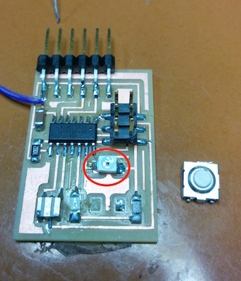
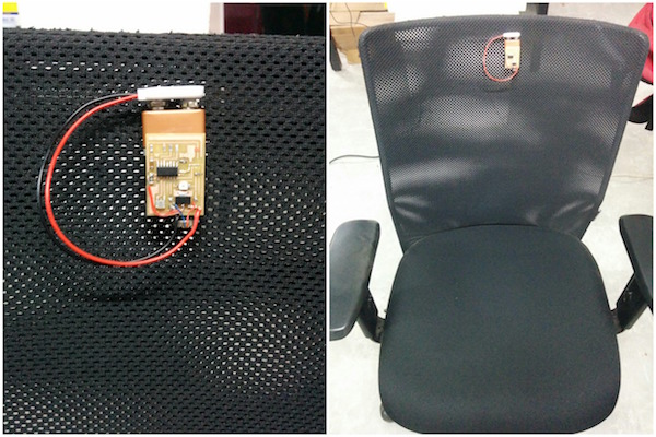
I started off by using my HelloWorld board milled from the Modella (the process can be seen here) and de soldering the button from it. I then attached the phototransistor to ATtiny pin no: 7. I found out that the notch in the package of the phototransistor represents the collector terminal. Reference: link1 and link2.
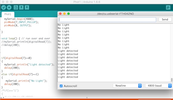
After soldering the npn phototransistor, I checked it using arduino. I used the following code to print serially: “No light” when the phototransistor was not exposed to light and “Light detected” when it was exposed:
#include <SoftwareSerial.h>
int v;
SoftwareSerial mySerial(0,1); // RX, TX

void setup() {
  // Open serial communications and wait for port to open:
  // set the data rate for the SoftwareSerial port
  mySerial.begin(4800);
  pinMode(7,INPUT_PULLUP);
  pinMode(8, OUTPUT);

}

void loop() { // run over and over
//mySerial.println(digitalRead(7));
//delay(200);


if(digitalRead(7)==0)
{
  mySerial.println("Light detected");
  delay(200);
}
else if(digitalRead(7)==1)
{
   mySerial.println("No Light");
  delay(200);
}
}
Next, I used a salvaged phone haptic motor to connect it to pin ATtiny pin no 5 (Arduino pin 8). And tested the motor by powering it up when there is no light and turning it off when there is.
A video of the working:
The code used:
#include <SoftwareSerial.h>
int v;
SoftwareSerial mySerial(0,1); // RX, TX
void setup() {
// Open serial communications and wait for port to open:
// set the data rate for the SoftwareSerial port
mySerial.begin(4800);
pinMode(7,INPUT_PULLUP);
pinMode(8, OUTPUT);//Motor
}
void loop() { // run over and over
//mySerial.println(digitalRead(7));
//delay(200);
if(digitalRead(7)==0)
{
mySerial.println("Light detected");
digitalWrite(8,LOW);
delay(200);
}
else if(digitalRead(7)==1)
{
mySerial.println("No Light");
digitalWrite(8,HIGH);
delay(200);
}
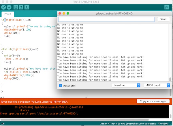
} Next, I wrote the code to activate the motor if a person is sitting for too long. Ideally, the value should be 10 mins, but for the ease of testing I am using 10 seconds. Here, if the controller detects no light for more than 10 seconds (in real case- 10 mins) the motor starts vibrating and indicates that the user needs to get out of the chair. The code:
#include <SoftwareSerial.h>
int v;
SoftwareSerial mySerial(0,1); // RX, TX
unsigned long time;
int i;

void setup() {
  // Open serial communications and wait for port to open:
  // set the data rate for the SoftwareSerial port
  mySerial.begin(4800);
  pinMode(7,INPUT_PULLUP);
  pinMode(8, OUTPUT);//Motor
 }

void loop() { // run over and over
//mySerial.println(digitalRead(7));
//delay(200);

if(digitalRead(7)==0)
{
  mySerial.println("No one is using me");
  digitalWrite(8,LOW);
  delay(200);
  i=0;
}
else if(digitalRead(7)==1)
{
  while(i==0)
  {time = millis();
  i++;}

  mySerial.println("You have been sitting for more than 10 mins! Get up and work!");
  if((millis()-time)>10000)
  digitalWrite(8,HIGH);
  delay(200);
  }
} 
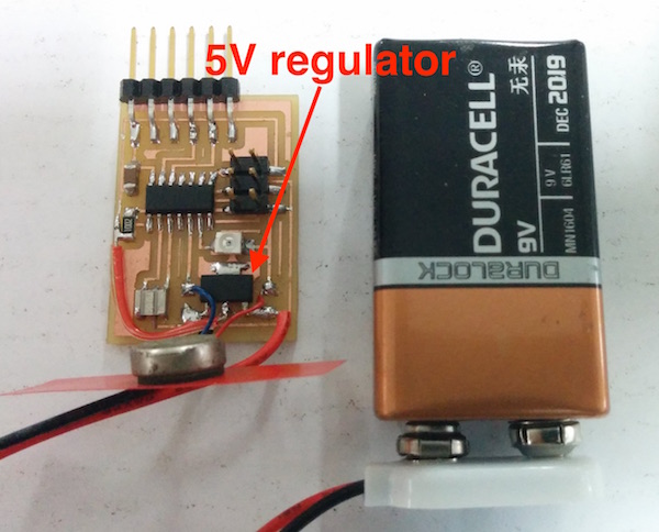
Next, I decided to add a 5V 1A voltage regulator to power the board using a 9V battery. For this, I used the ZLDO1117 regulator: link.Then, I added the clip for the 9V battery and looks like this:
A test video:
Then I removed the ISP and FTDI pins to make the board sleek:
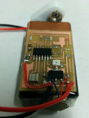
Testing the board on a temporary setup:
Designing and printing:
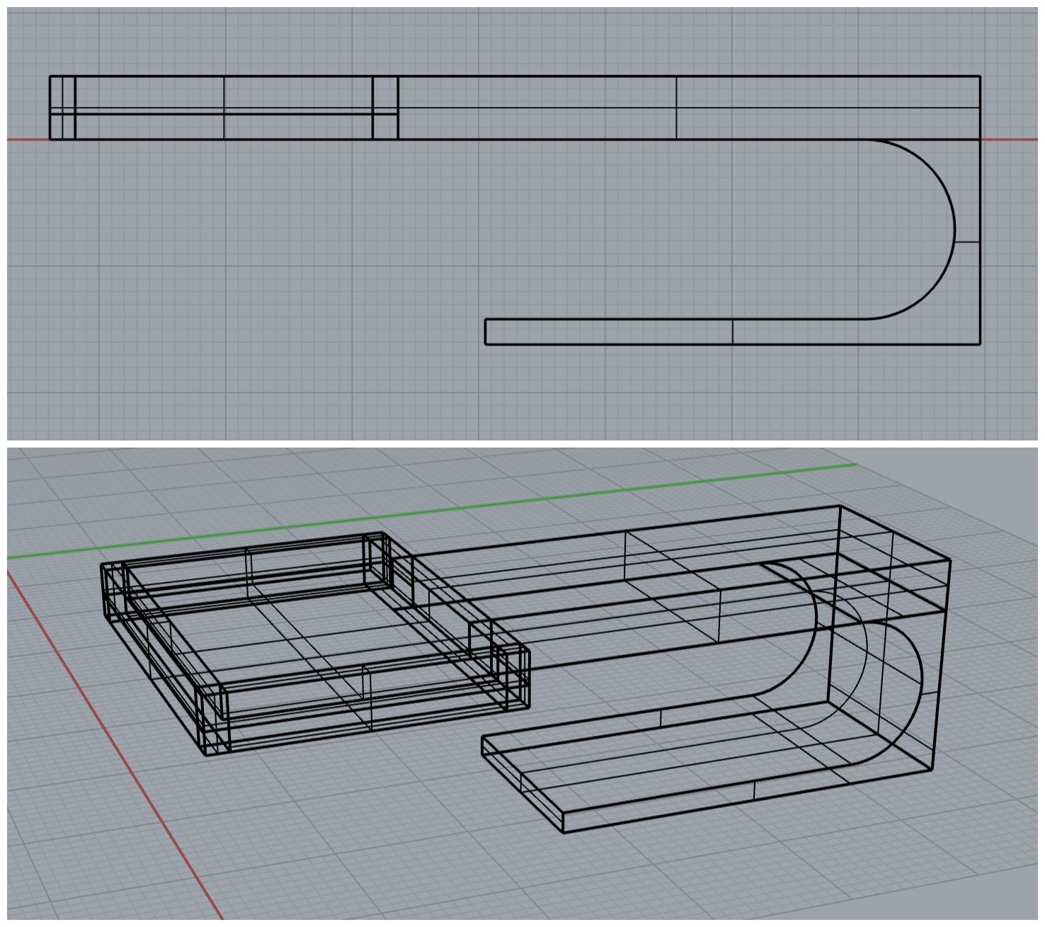
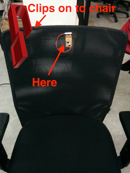
After I sorted out the electronics and programming part, I then moved on to designing the casing for the board that could be clipped on to the chair. I used Rhino for designing this.
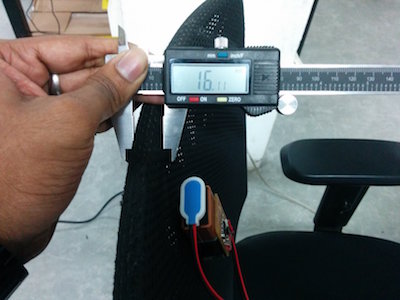
I started off by measuring the diameter of the chair’s edge (14.15mm), then the dimensions of the board (33x23.5mm). Based on these I started designing the case using polylines. Later, I converted the closed curves into a surface using surface from 3,4 pts function. And then extruded it to a height of 5mm.

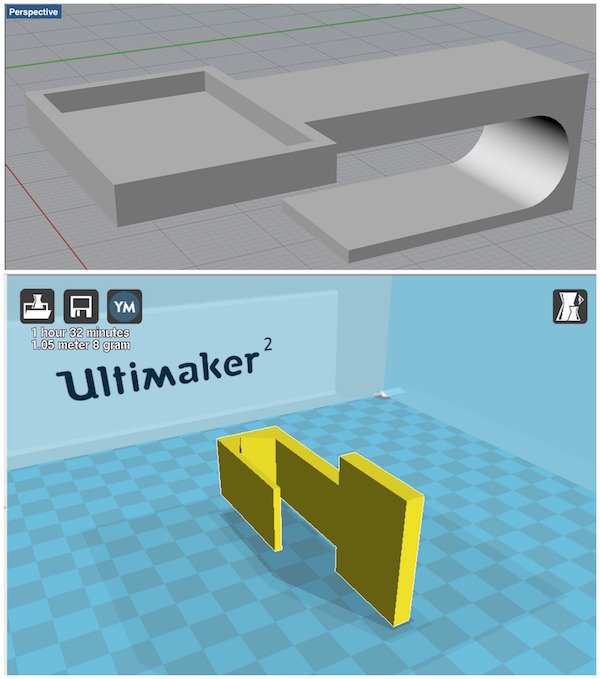
Next, I designed the hook for the case. I drew it using the polylines and circle function and then joined it into a closed curve. Next, I used the “Surface from planar curves” function to convert it into a surface and then extruded it to 20mm. This is how it looks:
Next, I will be printing the exported .stl file using Cura on the Ultimaker.
Download files: LazyMax.3dm, LazyMax.stl